
VDCForum Global Reality Capture and Level Of Acceptance (LOA) Specification
This specification combines both reality capture densities as well as tolerances. The Specification was produced from the results of both PhD research and detailed project case studies in laser scanning by Ascend and VDCForum Global Contributors. The 2025 version is currently available, and we are seeking Contributor input for the 2026 version that is scheduled to be available summer 2026.
Previous versions are located at the bottom of the page.
Level of Acceptance (LOA) Specification Version 2025
for Reality Capture and Simulation
December 2025
Dr. William F Ikerd, II, P.E., PhD, Principal Investigator and Author
VDCForum Global Director of Research & Education
Nothing contained in this work shall be considered the rendering of legal advice. Readers are responsible for obtaining such advice from their own legal counsel. This work and any forms herein are intended solely for educational and informational purposes. All images are intended to illustrate building conditions in compliance with common building codes. However, the images do not consider site specific conditions, regional building codes and other important information that may require a material change for specific projects. These illustrations do not make representation for fitness for a particular project nor for code or design compliance. Copyright © 2019-2025 by the author Dr. William F. Ikerd II, P.E. PhD. All rights reserve
Images courtesy of Ascend Building Knowledge Foundation, AscendBKF.org, used with permission. The Level Of Acceptance (LOA) scale, constructs and specification are authored and developed by Dr. Will Ikerd, P.E., PhD all rights reserved. They were developed with research from Ikerd Consulting, LLC and Ascend Building Knowledge Foundation. The LOA scale and construct are used by VDCForum Global with permission from the author to publish the VDCForum Global LOA Specification for Reality Capture and Simulation. The VDCForum Global LOA Specification for Reality Capture and Simulation use these LOA constructs with permission from the author to make them available to the public. To maintain the integrity and usefulness of these documents as a reference specification, certain restrictions apply to their use. These documents are licensed to the public under Creative Commons licenses as follows: Work is licensed under the Creative Commons Attribution-NonCommercial-NoDerivatives 4.0 International License with Attribution to the Author (http://creativecommons.org/licenses/by-nc-nd/4.0/). Licensing questions should be directed to info@BIMForum.Global
Background
The purpose of The VDCForum Global Level of Acceptance (LOA) Specification (The Specification) for Reality Capture and Simulation is to provide guidance for owners and their teams wishing to address reality capture of the built environment. The VDCForum Global Reality Capture and Simulation Taskforce (ReCap/Sim Taskforce) was formed to address the emerging trend in the areas of reality capture and simulation. Reality capture includes laser scanning, among other forms of measurement, for as-built documentation. Common tools and equipment used for reality capture includes, but are not limited to laser scanners, robotic total station, and point layout tools. Additionally, simulation includes but is not limited to virtual reality, augmented reality, and other related forms of simulation. The related simulation of 4D and 5D are addressed by the ReCap/Sim Taskforce in collaboration with the VDCForum’s Global Scheduling & Estimating Taskforce (4x5D Taskforce). The ReCap/Sim Taskforce is dedicated to improving documentation of the built environment, which includes but is not limited to building, GIS, civil infrastructure, equipment, and industrial projects. To learn more about the VDCForum’s Global Reality Capture and Simulation Specification please visit our website at bimforum.global/reality/ or contact the Director of Research & Education at info@BIMForum.global.
Overall Editing and Graphics Creation
Ascend Building Knowledge Foundation (AscendBKF.org)
VDCForum Global (BIMForum.Global)
IKERD Consulting, LLC.
Executive Summary
The Level of Acceptance (LOA) Specification is a reference tool intended to improve the quality of communication among users of Reality Capture and Simulation of the built environment about the characteristics of elements that are being documented. It is important to note that the built environment includes project types such as but not limited to equipment, civil, industrial, building, GIS and other infrastructure projects. The LOA Specification expands upon the VDCForum Global LOD Specification (LOD Specification) with the most recent version being the 2025 version. The LOA accomplishes this by providing definitions of the accuracy and reality capture density of elements being documented in the design and construction process. Since the inception of the LOD specification, the taskforce understood the need to address reality capture which is not addressed in the body of the LOD Specification. The LOA addresses this important topic of tolerances and measurement density that compliments the LOD Specification. While other specifications exist for building documentation, they do not address density, nor are they established for non-building documentation. Additionally, other specifications have the limitation of narrowly defined ranges of tolerances that do not reasonably address the large variety of tolerances that are common to projects in the built environment. This specification is one of the first specifications to provide both tolerances and measurement densities that are needed on all types of projects in the built environment. As background, Building Information Modeling (BIM) presents information about a construction project or structure in the form of three-dimensional graphical representations of elements (e.g., doors, beams, etc.), which can be further associated with information about other characteristics of those elements. It is possible for the graphical representation of an element, taken alone, to suggest that greater accuracy or intention can be attributed to the element than is in fact the case. The VDCForum Global LOA Specification was developed to provide a systematic way for owners and their teams to establish the reality capture requirements to document real world conditions of the BIM that teams are using. Discussions within the VDCForum Global lead to the creation of a multi-disciplinary task force to develop and maintain the LOA Specification. Users of the LOA Specification are cautioned that it does not prescribe the necessary levels of acceptance for different elements in the built environment. That determination is left to each project team in their BIM Execution Plan’s (BxP, BEP) (sometimes referred to as a Project Execution Plan (PEP) BIM Requirements. It is believed, however, that the availability of more precise definitions will reduce the risk of miscommunication among project teams’ members. This is achieved when the expectations are established, through easier identification of what each team member is expected to deliver. The Specification will help create greater predictability of the level of effort that is required to create reality capture deliverables. The LOA Specification is organized by allowing the user to define the elements of interest that are to be documented with reality capture. The user may elect to use CSI Uniformat 2010, with the subclasses expanded to Level 4 (and in a few cases to Level 5) to provide detail and clarity to the element definitions.
The LOA Specification does not prescribe who the author of a particular component at a given LOA should be, as that will vary from one project to another. However, the document does provide a concise schematic means through the spreadsheet in Part II for a project team to identify element tolerances and reality capture densities, again in the interest of improving communication among model users. In addition, the Reality Capture and Simulation task force has been working with software developers to provide a means within the software of tagging individual elements within a model with their current LOA level. The LOA Specification is intended as a reference standard but is also intended to evolve as the use of reality capture and simulation develops. The Specification is updated annually, and previous versions are maintained on the BIMForum Global website (bimforum.global/reality/). Users are invited to provide comments and recommendations for consideration in future editions. These should be sent by email to info@BIMForum.Global.
Background on VDCForum Global’s New 2022 LOA Specification
Ascend Building Knowledge Foundation (Ascend) was formed in 2017 and was recognized as a 501c3 non-profit organization the following year. The Associated General Contractors of America (AGC) published some of the earlier United States (US) based BIMForum LOD Specifications (AGC BIMForum). The principal investigators of this document collaborated with and chaired sections of AGC BIMForum’s LOD specification from 2012 until AGC ended financial support and divested AGC from the original AGC BIMForum in 2019. In the fall of that same year, Ascend assisted with the formation of a newly incorporated Philadelphia, PA based BIMForum (BIMForum-Philadelphia) by providing graphics support and staffing of booths at conferences such as the Design Build Institute of America (DBIA) conferences in 2019 and online events following the Covid-19 pandemic. Ascend also assisted with some of the graphics in the BIMForum-Philadelphia LOD Specifications of 2020 and 2021. During this time frame, Ascend and its board members assisted other BIMForums and similarly aligned BIM groups in Latin America in Spanish as well. This Level of Acceptance (LOA) Specification builds on Ascends work in reality capture research since 2017 and is formed in a way that is synergistic with BIMForum Gobal’s new LOD Specification with scales from 100 to 500 for Model Element reliability.
Introduction to Level of Acceptance (LOA)
The Level of Acceptance (LOA) Specification is a reference tool intended to improve the quality of communication among users of reality capture and simulation in the built environment. One way this is achieved is by defining the characteristics of elements that are being documented. It is also important to note that the built environment includes project types such as, but not limited to, equipment, civil infrastructure, industrial development, building, GIS and other infrastructure projects. It is with this goal that the LOA Specification expands upon the VDCForum Global LOD Specification. The LOA accomplishes this by providing definitions of the accuracy and reality capture density of elements being documented in the design and construction process. Since the inception of the LOD specification, the taskforce understood the need to address reality capture which is not addressed in the body of the LOD Specification. The LOA addresses this important topic of tolerances and measurement density that compliments the LOD Specification. While other specifications exist for building document documentation, they do not address density, nor are they established for non-building documentation. Additionally, other specifications have the limitation of narrowly defined ranges of tolerances that do not reasonably address the large variety of tolerances that are common to projects in the built environment. This specification is one of the first specifications to provide both tolerances and measurement densities that are needed in all types of projects in the built environment. For an introduction to this specification, please visit BIMForum.global to view the 2019 September conference presentation originally provided in St. Louis, MO providing an overview of the specification.

Figure 1: Author’s Level of Acceptance (LOA) specification originally presented and published at the AGC BIMForum 2019 conference in St. Louis, MO on Sept. 17. For an expanded introduction to this specification, please visit BIMForum.Global/Reality to view the updated content from the Author’s original 2019 September AGC conference presentation in St. Louis, MO that provided an overview of the specification.
Specification Table
The LOA Specification table is shown below.

Figure 2: BIMForum Global Specification table.
Table Definition
Element Category i: This would identify the ith (element categories 1-4 in the example above) elements being measured. Project teams often will use CSI Uniformat for a more complete list of elements while rather straightforward projects may simply call out a few of the main element items in question (for example walls, ceilings, floors, etc).
Vc-tol: This field is for the vertical reality captured tolerance. This is the upper limit of tolerance for measurements assuming a 95% confidence level.
Hc-tol: This field is for the horizontal reality captured tolerance. This is the upper limit of tolerance for measurements assuming a 95% confidence level.
d: Density is a measure of the number of points in a given area. This reports the minimum density required on the element in question. The default in the specification is measured in points per square inch. Note that measured densities often vary based on how close the object is to the equipment creating the measurements.
g: Gap is the distance between given measurements.
Vc: Validation of the measurements. This is signified as 0 for non-validation. 1 represents using one method to compare different measurement of the same element for validation. 2 represents the use of 2 or more different methods of measuring equipment to compare measurements of the same element.
Vs: Validation of Simulation (Modeling). This is similar to Vc.
Example:
The following table provides an example of how the LOA can be used with the BIMForum Global LOD Specification. It combines the Reality Capture Specification table with the LOD Specification table for scan to BIM applications. Areas edited in the table are highlighted in yellow.

Figure 3: Example of BIMForum Global Reality Capture Taskforce Level Of Acceptance (LOA) combined with the BIMForum Global Level Of Development (LOD) Specification. This example is provided and used with permission from Ascend Building Knowledge Foundation as part of the LOD Sample Model Training Curriculum, copyright 2020.
Commentary
The example above represents a Level of Acceptance (LOA) table for reality capture filled out for simple architectural area modeling. Note that the elements are defined as walls, ceilings, floors, and other visible building elements. Additionally, both vertical and horizontal reality capture tolerances were set at ± 2”. Most applications will typically have similar tolerances for Vc-tol and Hc-tol. The densities for these were selected to be relatively low, at four points per square inch. This would be an acceptable range to discern general wall, ceiling, and floor locations.
If the project required more refined details, a higher density scan would have been specified. Such details might include, but are not limited to, small items such as receptacles, fireproofing fixtures, and other similar smaller details in the space. Additionally, projects requiring analysis such as floor flatness studies may need much tighter tolerances and higher densities. The corresponding gap spacing between laser scan points is derived from the scan density. It is noted that no separate instrument validation is required for this work.
The simulated specification for modeling to be created from the reality capture is shown in the “simulated” section of the table. The tolerances for modeled work are ± 2”, which match the reality captured tolerances. Note that it would be inappropriate to require a tighter modeled tolerance in the Specification than what was captured in the reality capture tolerances.
Glossary and Key Concepts:
VDCForum Global’s Ten (Recommended) ‘Rules’ of LOD
The following ‘rules’ of LOD are provided in this commentary on Level of Acceptance (LOA) of Reality Capture for context as it relates to element modeling. These are applicable to modeling and simulation of element LODs developed from the reality capture.
Regardless of the LOD definitions used in a project’s BIM section of its Project Execution Plan (PEP), the BIMForum Global (BFG) Principal Investigators (PIs) of this LOD Specification have developed the following ten (recommended) ‘rules’ that LOD definitions ‘should’ follow. These are the ‘ten commandments’ that the PIs use to moderate and consider the discussion of proposed updates among contributors of the LOA and LOD Specifications.
1) LOD IS NOT FOR A WHOLE MODEL; IT ONLY APPLIES TO ELEMENTS IN A MODEL.
There is no LOD of a whole model. A model is a collection of Model Elements (MEs) at different LODs in a given phase of the project. The only exception to this rule is at an LOD 100 mass model of a building, for example where distinct MEs for building components can only be referred to by inference. However, even in this example, there will typically be a mass model of the site (Civil), the overall building (architect), and perhaps general structural system (structural) at LOD 100 in a federated model. In such cases, LOD 100 would apply to each of the mass models consisting of a single Model Element (ME).
2) LOD ≠ PROJECT PHASE
There is no LOD of a whole model. A model is a collection of Model Elements (MEs) at different LODs in a given phase of the project. The only exception to this rule is at an LOD 100 mass model of a building, for example where distinct MEs for building components can only be referred to by inference. However, even in this example, there will typically be a mass model of the site (Civil), the overall building (architect), and perhaps general structural system (structural) at LOD 100 in a federated model. In such cases, LOD 100 would apply to each of the mass models consisting of a single Model Element (ME).
3) LOD 000 = NO MODELING IS SCOPED FOR A GIVEN CLASS OF ELEMENT.
In the BIMForum Global LOD Specification, LOD 000 signifies that there is no Model Element (ME) requirement for the given class of element. It also signifies that there is not any scope for the element to be referenced by inference for the class of element from an overall LOD 100 mass model. This level is important in contractual scoping of elements that are excluded from the Model Element Authors (MEAs) scope.
4) LOD 350 is for Detailed Coordination Between Model Element Systems
After elements are developed to their specific LOD 300 geometry, detailed coordination typically must take place before the elements can be developed to full LOD 400 fabrication level. The principal investigators of the LOD Specifications recognized early in the use of some of the 2008 LOD definitions that there was a critical step in the BIM process that warranted an intermediate LOD between 300 and 400. This work is documented in their publications and presentations leading up to their 2012 proposal for the LOD 350 definition to be adopted for the first time in a national LOD specification. The original steel column example is provided in the following section to further explain the role of LOD 350.
5) A HIGHER LOD # IS NOT ALWAYS BETTER
The best LOD for an object is the LOD that meets the current project requirements and usage. There is no value in modeling elements to a higher LOD if this additional effort does not provide a clearly defined purpose at the given time.
For example, if a project is conducting typical trade coordination with Cold Formed Metal Framing (CFMF, metal studs) in walls, then LOD 350 Model Elements (MEs) that show the studs, but do not include the screw fasteners, is acceptable. In such a case, it could be considered a waste of time and money to model the system to LOD 400 (full fabrication) with screws for simply checking coordination around the framing, which was modeled at LOD 350. However, if the CFMF is a part of a 4D sequenced virtual mockup in an isolated area that is being used as part of a Building Enclosure Review Meeting, then LOD 400 may be the appropriate level for the metal studs. In these cases, the sequencing of when screws are being installed in relation to the water proofing membrane, for instance, can be critical. See Figure 4 below.

Figure 4: Sample images of Cold Formed Metal Framing (CFMF) from BIMForum Global LOD Specification. Note that at LOD 350 only studs are modeled, whereas connection fasteners are included at LOD 400.
6) Model Element (ME) Information Requirements Must be Defined in the BIM PEP
Associated Model Element information is very specific for the given use case of a given BIM in a given project for a given Project Owner. Non-Graphic Information (NGI) may be associated with a Model Element (ME). If NGI has a different level of reliance than the ME LOD to which it is attached, then the Model Element Author (MEA) shall indicate the difference in the BIM section of the PEP.
7) ME Must Meet All 5 Distinguishing Geometric Characteristics for a Given LOD:
Model Element Geometry is distinguished by 5 key characteristics, and if one of the 5 is less developed than the minimum requirement of a given LOD, the ME fails to meet that given LOD. For example, if a steel column is modeled ‘specific’ within the given tolerances for structural steel for size, shape, quantity, orientation, but is merely ‘approximate’ in its location, then that column does not meet the LOD 300 (‘specific’) criteria and is therefore considered to be at LOD 200 (‘approximate’). For the steel column in this example to meet the requirement of LOD 300, it must be modeled ‘specifically’ within the project specified tolerances for all 5 LOD Distinguishing Geometric Characteristics:
-
- Quantity
- Size
- Shape
- Location
- Orientation
8) Tolerances of MEs are Defined by Reference of the Elements Material/Industry Standards
All tolerances in LOD definitions should defer to industry standards that are incorporated by reference in a given projects specifications. The nature of 3D modeling is that all elements are precise even though they may not be accurate. Additionally, most modeling platforms in common use are static state modelers that do not account for real world dynamic conditions such as, but not limited to, deflection, camber, thermal expansion/contraction, thickness of fire proofing, thickness of insulation (in some cases), wind deflection, live loading, long term material creep, and material shrinkage. For example, such effects can be notable when considering the interface of systems such as glass and aluminum curtain wall on high-rise concrete buildings. Project Owners’ teams should address such tolerance topics in the BIM section of the PEP.
9) Measurement of ME Accurately Within Tolerance is Only for LOD 300~400.
Because LOD 200 is approximate, only LOD 300 through LOD 400 can be measured directly from the model within the elements project specified tolerances. Unless noted otherwise, the tolerances for a given element are defined by that industries fabrication, manufacturing, erection, and installation tolerances. All such tolerances should be clearly defined by reference in the project specification for each element material and incorporated by reference in the BIM section of the PEP.
10) LOD 500 Model Elements Are Based on LOD 100~400 Geometry
The BIM section of the PEP should define if an LOD 500 element is documented by reference with an inference in LOD 100 overall mass model or defined with LOD 200, 300, 350 or 400 Geometry. This is why the ability of measuring MEs directly from a model at LOD 500 will vary depending on the geometric basis of the LOD 500 object.
For example, consider an existing basement wall inside a building that is modeled from as-built reality capture laser scan data on the interior side of the wall without any destructive testing to know the core of the wall or wall thickness. The models may have some historic drawings that indicate the design thickness of the wall and the Model Element Author (MEA) may use this information to assume an ‘approximate’ thickness of the wall. As such, a wall’s geometry could only be defined as LOD 200 (reference BFG LOD Rule #7). In this case, such a wall would be an LOD 500 wall with geometry to LOD 200, and only the inside face that was laser scanned could be measurable directly from the model.
Also, a Model Element at LOD 500 does not have any higher level of geometry than an element at LOD 400. For this reason, the BIMForum Global LOD Specification does not show any additional graphics beyond LOD 400 for a given element.
LOD 350 Example, The Steel Column 2009-2012


Figure 5: Published 2012 slides from national conference. This image was used to illustrate the author’s concept of LOD 350 that was later presented to the AGC for adoption in the first US national graphical LOD specification.

Figure 6: Image shown in ENR, Post, N, April 25, 2018 “At Structural Congress, a Call for Designers to Mitigate BIM-Project Risk.” The image was used to delineate the distinction between LOD 300, 350, and 400 of a steel column, relative to the information shown in the example 2D typical detail that would be found in a project’s Construction Documents (CD) issued for permit.
Glossary and Key Concepts:
The following are applications of the BIMForum Global Ten Fundamental LOD Rules using the original steel column example. Non-Graphical Information is addressed in VDCFG LOD Rule #6. Each project team should establish the LOD definitions used for a given project in the Contacts and BIM sections of its PEP. In the absence of such a definition, the following LOD definitions shall apply when this Specification is adopted by reference.
| LOD | Summary Concept | Element Accurately Measured from Model at given LOD & LOD 500 | Sample Definition | Sample Image |
| 000 | NO BIM | N/A | No distinct Model Elements (MEs) exist, AND No inference can be made from an overall mass for these elements at this LOD in this system. |  |
| 100 | CONCEPTUAL / INFERED |
NO (No Element Exists at this LOD) |
No distinct model elements exist but inference about elements can be made from an overall mass at this LOD. The Model Element (ME) may be inferred or referenced in the model with a symbol or other generic representation, but the ME does not satisfy the requirements for LOD 200. |  |
| 200 | APPROXIMATE | NO (ME only Approx.) |
The Model Element (ME) is modeled approximately in terms of one or more of the following characteristics: quantity, size, shape, location, OR orientation | 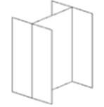 |
| 300 | SPECIFIC | YES within ME Project / System Tolerances |
The Model Element is modeled specifically within the project’s tolerances for its system in terms of ALL of the following characteristics: quantity, size, shape, location, AND orientation. |  |
| 350 | DETAILED COORDINATION | YES within ME Project / System Tolerances |
The Model Element (ME) is modeled specifically per LOD 300 AND includes interfacing features with adjacent and/or dependent model elements to facilitate detailed coordination between systems. |  |
| 400 | FABRICATE | YES within ME Project / System Tolerances |
The Model Element (ME) is modeled with details required for fabrication, manufacturing, assembly and installation. | 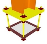 |
Notes for LOD 500
LOD 500 should be thought of as a special condition of LOD’s 100, 200, 300, 350 and 400. The AS-BUILT state of LOD 500 for a model element may be based on element geometry and detail any of the LOD’s 100 through 400.
| LOD | Summary Concept | Element Accurately Measured from Model at given LOD & LOD 500 | Sample Definition |
Sample Image |
| 500 | AS-BUILT | VARIES if geometry is LOD 100-200 vs 300~400 | The Model Element (ME) is modeled in its as-built or existing state within the tolerances that are defined for the project. The ability to measure the object depends on which LOD its geometry is based on. | ME Geometry could be that of LOD 100, 200, 300, 350 OR 400 |
Additional Terms
Element Category i: This would identify the ith elements being measured. Project teams often will use CSI Uniformat for a more complete list of elements while rather straightforward projects may simply call out a few of the main element items in question (for example walls, ceilings, floors etc).
Vc-tol: This field is for the vertical reality captured tolerance. This is the upper limit of tolerance for measurements assuming a 95% confidence level.
Hc-tol: This field is for the horizontal reality captured tolerance. This is the upper limit of tolerance for measurements assuming a 95% confidence level.
d: Density is a measure of the number of points in a given area. This reports the minimum density required on the element in question. The default in the specification is measured in points per square inch. Note that measured densities often vary based on how close the object is to the equipment creating the measurements.
g: Gap is the distance between given measurements.
Vc: Validation of the measurements. This is signified as 0 for non-validation. 1 represents using one method to compare different measurement of the same element for validation. 2 represents the use of 2 or more different methods of measuring equipment to compare measurements of the same element.
Vs: Validation of Simulation (Modeling). This is similar to Vc.