BIM Execution Plan Guide
The Guide is for building owners and their design and construction teams who are new to Building Information Modeling on small to midsized projects. It is an aid in introducing fundamental concepts of BIM Execution Plans and the BIM aspects of Project Execution Plans (PEP). Teams sometimes abbreviate BIM Execution Plans as either BEP or BxP in industry documents that our taskforce has reviewed. In The Guide we will use the abbreviation “BxP” to refer to BIM Execution Plans or the BIM aspects of Project Execution Plans (PEP). Additionally, we will use “The Guide” to reference this document.
The purpose of The Guide is to introduce BxP concepts to teams on the smallest of projects that may have some team members who have never previously used BIM.
The principles and practices in The Guide were developed based on interviews and survey responses from over five hundred industry practitioners, including Owners’ and Facility Management team members, design and construction team members, trade partners, detailers, manufacturers, and legal professionals. Furthermore, the professionals who provided input for The Guide represent a diverse selection of firms with varying sizes and locations. This diversified pool of contributors provided a wide overview of the current use of BxPs in the A/E/C/O/FM industry from which the very best of best practices were distilled.

BIM Execution Plan
October 2025
Dr. William F Ikerd, II, P.E., PhD, Principal Investigator and Author
VDCForum Global Director of Research & Education
Introduction
The Guide is for building owners and their design and construction teams who are new to Building Information Modeling on small to midsized projects. It is an aid in introducing fundamental concepts of BIM Execution Plans and the BIM aspects of Project Execution Plans (PEP). Teams sometimes abbreviate BIM Execution Plans as either BEP or BxP in industry documents that our taskforce has reviewed. In The Guide we will use the abbreviation “BxP” to refer to BIM Execution Plans or the BIM aspects of Project Execution Plans (PEP). Additionally, we will use “The Guide” to reference this document.
The purpose of The Guide is to introduce BxP concepts to teams on the smallest of projects that may have some team members who have never previously used BIM.
The principles and practices in The Guide were developed based on interviews and survey responses from over five hundred industry practitioners, including Owners’ and Facility Management team members, design and construction team members, trade partners, detailers, manufacturers, and legal professionals. Furthermore, the professionals who provided input for The Guide represent a diverse selection of firms with varying sizes and locations. This diversified pool of contributors provided a wide overview of the current use of BxPs in the A/E/C/O/FM industry from which the very best of best practices were distilled.
Origin
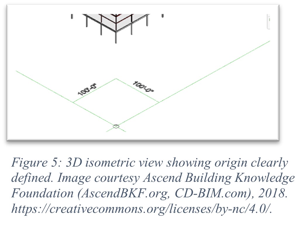
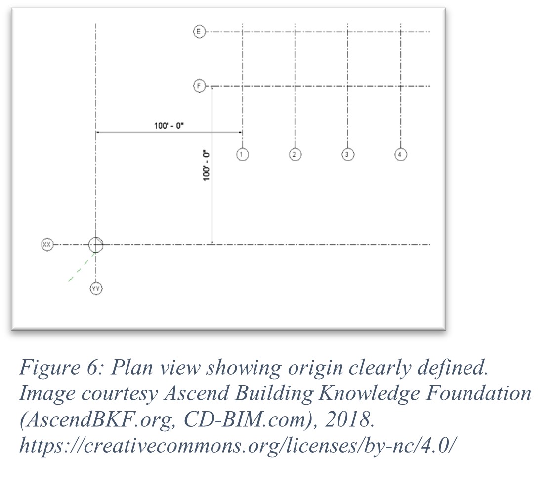
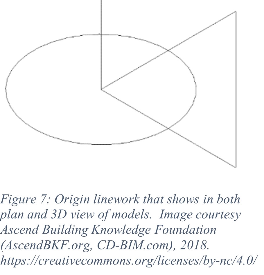
The project general notes of the design drawings and specification should clearly define the local relative Building X, Y, Z coordinates that other trades will use in construction and that are coordinated with the structural model. Generally, the X,Y coordinates of the origin should be defined relative to the Southwest most column grid intersection with a South and West offset of 10,100 or 1000 feet depending on the project size. The Southwest column intersection is chosen so the structure is in a positive X-Y coordinate system (i.e. quadrant 1 of a cartesian coordinate grid system). The offsets of 10, 100 or 1000 feet South and West of the origin are so that any portions of the building that extend South or West of the project origin grid intersections will also be within a positive X-Y coordinate system. Reference the figures 5 – 7.
The Z elevation should be defined as 0, 100′ or absolute elevation depending on firm preference. It is common to use a relative 100’ elevation. Plan North is established as being in the positive Y direction. Many firms will define grids “XX” and “YY” that locate The Origin point of 0,0 relative to the project’s other grid systems shown in the construction document. Additionally, these elements should be modeled to scale without rounding in their associated dimension strings.
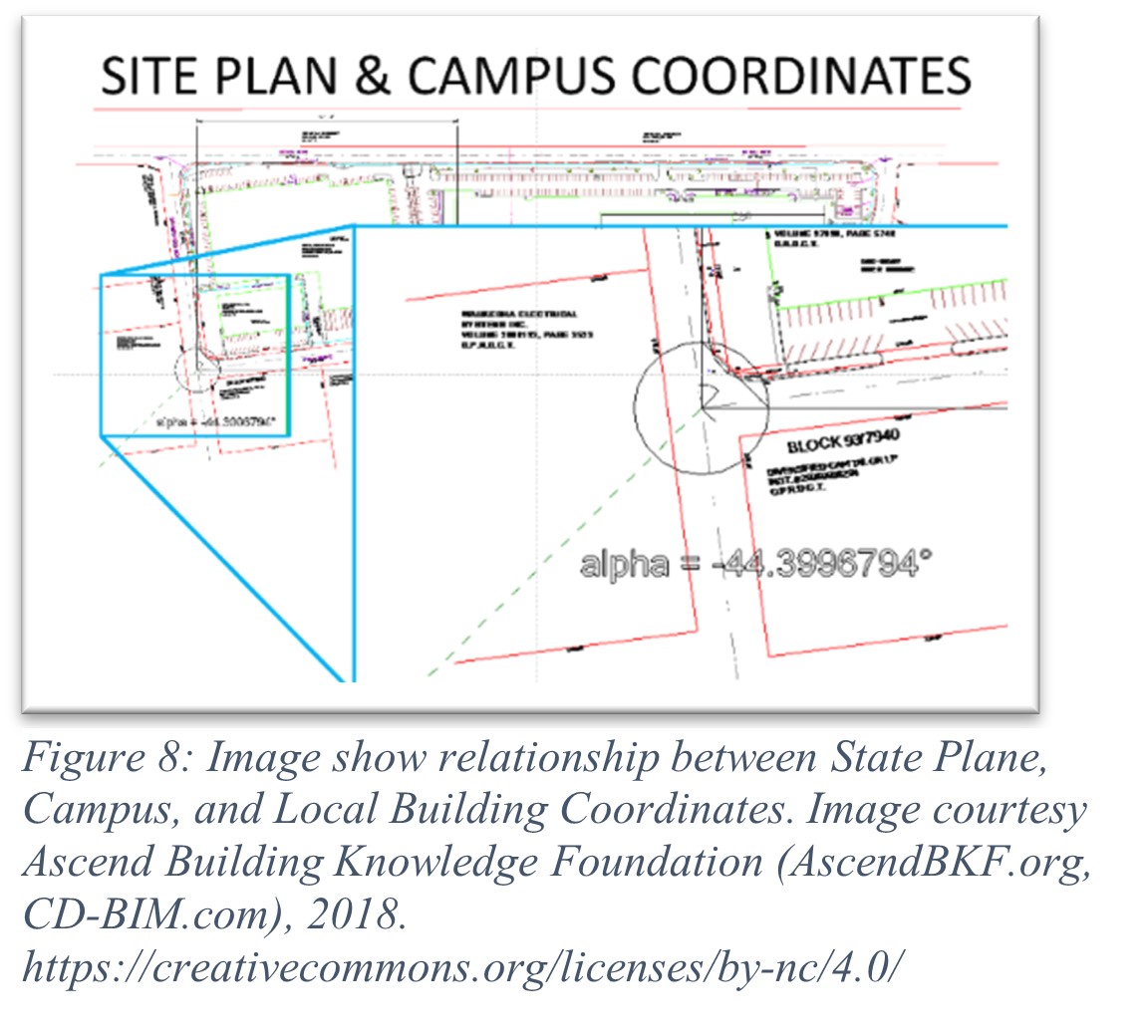
The BIM BxP should document the relationship between Object, Building, Campus, and State Plane coordinate systems.
The rules above form the basis of the project’s “local” relative Building coordinate system that can become part of the legal definition in the construction documents and contracts related to the model and references to LOD. It is recommended that the design BxP clearly state the project origin information and that this design BxP is transmitted with the BIM to the owner and construction team when the models are shared. This process aids in linking the structural model to third party applications that are based on traditional CAD coordinate systems and, later, to field layout during construction. A benefit of defining the local relative origin early and stating it in the project’s general notes is that other models that are developed for shop drawings from the construction documents have a point of reference to follow when they are submitted for review. This local relative building coordinate system is also tied back to the civil engineers’ state plane coordinate system, which is referred to as the state plane coordinates.
Projects may also have a Campus coordinate system normally near the Southwest corner of the project site. There can also be an Object coordinate system used for items such as equipment models. This Object coordinate system is typically referenced relative to the Local Building coordinate system in the form of a grid line offset and floor elevation offset. The Civil coordinate system defined by the state plane absolute coordinate system will then have a set relationship of an X, Y, and Z offset and a Z-axis rotation with The Local Building coordinate system as defined by the Design Team. Using this set relationship between the Civil absolute and relative Building coordinate systems, all federated project models can be easily converted to absolute or relative systems depending on the owner’s preference in their facility management models. Ideally, the owner will have clearly written documentation in the BIM Execution Plan that accurately defines the relationship between Object, Building, Campus, and Civil coordinate systems.
In summary, these 5 coordinate systems are:
- Object: relative system that defines items such as assemblies and equipment in the structure. For example, the Air Handler Unit will have a relative Object coordinate that references the Local Building coordinate, which defines the mechanical room it resides in.
- Building Local: relative coordinate system of the building defined so that the entire building is in positive point coordinates.
- Campus, Site: relative coordinate system of the building’s site defined so that the entire site is in positive point coordinates.
- State Plane: Absolute coordinate system with Northing and Easting used by surveyors and civil engineers. This is also used by owners tying in their BIM to GIS applications.
- GPS: Absolute coordinate system with Northing and Easting used by surveyors and civil engineers. This is also used by owners tying in their BIM to GIS applications.
- Importance of Structural and Civil Engineers’ Input in Grid Line Systems
A Project’s structural engineer needs to be able to set the LOD of the origin of the project with the Architect at the end of the DD phase of the project. The entire construction process will begin with the structural engineer’s foundation systems and the gridlines shown on the structural design drawings. Unless differences are discovered in the design and modeling process between structural and architectural grid lines, actual architectural content will be formed around the in-place structure that is built. This is an important reason for teams to invest time in verifying that origins and grid systems are confirmed and coordinated in the design models. Additionally, this needs to be coordinated with the civil engineer and site surveyor’s state plane coordinates. Following this, manufacturers will reference the building coordinates for the placing of their content.
Levels
The BIM should be broken up and coordinated by levels over the project. It is recommended that The Project Team define this in their BxP for both design and construction. Typically each level is defined as the model space from finish floor (FF) of one level to finish floor (FF) of the level above. An example from the CD-BIM Sample BxP, based on the CD-BIM Sample Model, is as follows:
Zone L00: Below 100’-0”
Zone L01: EL= 100’-0” to 116’-4”
Zone L02: EL= 116’-4” to 130’-4”
Zone L03: EL= 130’-4” to 144’-4”
Zone L04: EL= 144’-4” to 161’-0”
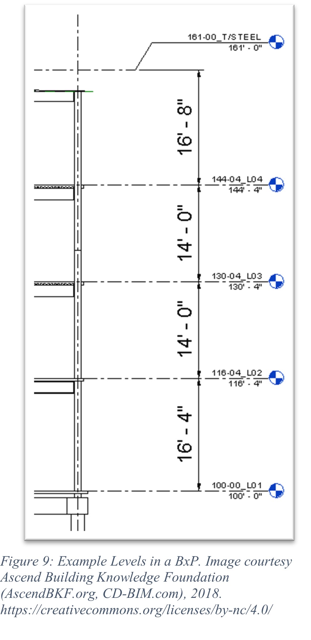
Project Plan Areas and Zones
Defining project zones helps the VDC effort by dividing the model levels into manageable portions of the building that can be reasonably analyzed for coordination. It is recommended that the zones of the levels follow the labels of the plan areas used in the construction documentation. A zone typically consists of a portion of the building that fits on an architectural E1 30”x 42” plan sheet at 1/8” = 1’-0” scale. This would typically be equivalent to approximately 30,000 to 36,000 square feet of space. For example, if one level of a building design used 3 plan sheets at 1/8” scale noted as areas A, B, and C for the second floor, then the BxP could have zones L2-A, L2-B, and L2-C, respectively, defined by the plan areas and extending from the finish floor of level 2 to the finish floor of level 3 in the model. This general rule of thumb may vary considerably from project to project and from team to team. Many industry practitioners who have contributed to The Guide have noted that the amount of model content in a zone over one level of the building is an appropriate amount of content to address in a 1 to 2-hour construction coordination meeting. Some construction teams may coordinate more than one zone per meeting for simple building types. More complex building types, such as hospitals, may require multiple meetings per zone to coordinate.
